|
A Generalized Vertex Truncation Scheme to Construct Intriguing Polyhedral Shapes Ergun Akleman, Paul Edmundson and Ozan Ozener Visualization Sciences Program, 216 Langford Center, Texas A&M University College Station, Texas 77843-3137, USA. email: ergun@viz.tamu.edu
Abstract
1. Introduction One of the most exciting aspects of shape modeling and
sculpting is the development of new algorithms and methods to create unusual,
interesting and aesthetically pleasing shapes. Recent advances in computer
graphics, shape modeling and mathematics help the imagination of contemporary
mathematicians, artists and architects to design new and unusual 3D
forms
[11]. In this paper, we present such an unusual class
of polyhedra that are contradictorily interesting, i.e. they are smooth
but yet C1 discontinuous. To create these shapes we apply a polyhedral
truncation algorithm based on Chaikin's scheme to any initial manifold
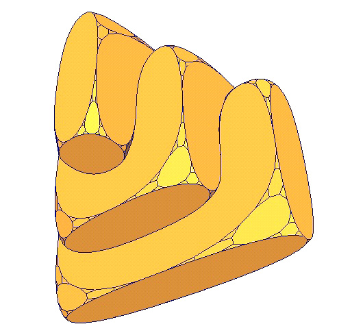
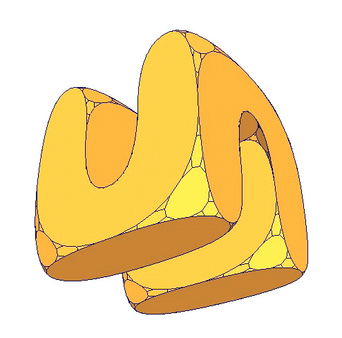
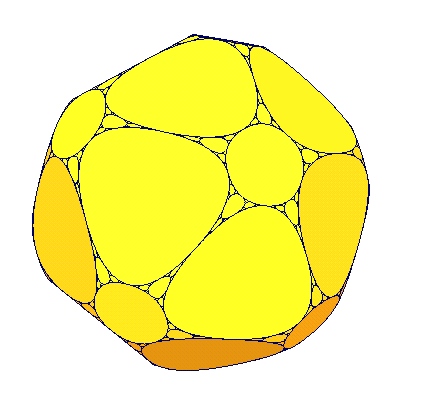
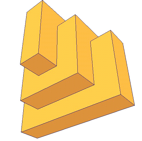
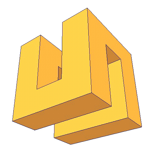
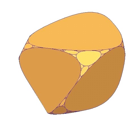
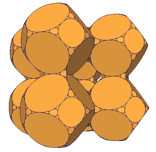
mesh. Figure 1 shows two shapes that are created by using
our approach.
Figure 1: Two examples of smooth-fractal
polyhedra that are created by our system.
2. Background One of the most notable artists of the last century, Escher, frequently applied mathematical concepts to create drawings of unusual 3D forms [6]. With the advance of computer graphics, many artists have begun to use mathematics as a tool to create revolutionary forms of artworks. There currently exist many contemporary artists such as George Hart [8], Helaman Ferguson [7], Bathsheba Grossman [9], Brent Collins and Carlo Séquin [20] who successfully combines art and mathematics to create unusual sculptures. These mathematical sculptors, who have a very noticeable presence in today's art scene, develop their own methods to model, prototype and fabricate an extraordinary variety of shapes. Unusual shapes are especially interesting for architectural design. Interestingly shaped architectural structures are symbols of cities, regions, states, and even countries. In fact, recent advances in computer graphics and shape modeling help the imagination of contemporary architects to design new forms [11]. One most notable contemporary example of interestingly shaped buildings that have become symbols is Frank Gehry's Guggenheim Museum. The Museum, with its stunning titanium-clad forms, has been credited with vitalizing an entire city and region of Spain. One of the major mathematical approaches to design unusual shapes is Fractal geometry. As told by Mandelbrot [12], Fractal geometry is often described as a "New Form of Art". Mandelbrot not only does not reject this idea, but he supports it by saying that "[with fractal geometry] all we do deal with is a new form of the controversial but ancient theme that all graphical representations of mathematical concepts are a form of art." Fractal geometry also introduced many new 3D forms such as Sierpinsky tetrahedron, Menger sponge, 3D subsets of 4D quaternion Julia and Mandelbrot sets. Shortly after their introduction by Mandelbrot, fractals have been widely used in contemporary architectural design. A large number of international architects such as Peter Eisenmann, Greg Lynn, Asymptote, Charles Correa, Coop Himmelblau, Carlos Ferrater, Arata Isozaki, Charles Jencks, Morphosis, and Eric Owen Moss have produced fractal rich contemporary architectural designs [1,10,14,15,16,17]. We can add some other designers like Karl Chu [22,13] who are concerned with genetic algorithms like L-systems or cellular automata. Architecture researchers also discovered that even before introduction of fractals, there exist many architectural examples that are rich in fractal aspects like facade environment relation in some vernacular dwellings [4], plan layouts and mass structures in the styles of modernistic architects such as Frank Lloyd Wwright, Mies Van Der Rohe [15] . Our 3D forms are closely related one of the earliest known 2D
fractal forms called Leibnitz packing of a circle (which themselves are
a special case of an earlier form called Apollonian nets and gaskets) [12].
According to Mandelbrot, Leibnitz described it in a letter saying that
"Imagine a circle; inscribe within it three other circles congruent to
each other and of maximum radius; proceed similarly within each of these
circles and within each interval between them, and imagine that the process
continues to infinity..." Our operations convert each vertex of an initial
polyhedron to a 3D form which looks similar to Leibnitz packing.
3. Methodology Shape construction algorithms of fractal geometry are often given by
a set of rules that are applied to an initial shape (see [3]).
The problem with these shape construction algorithms is that they are hard
to generalize. Each algorithm approaches its target shape regardless of
the shape of the initial object. These algorithms do not allow construction
of different target shapes from different initial shapes. Subdivision schemes
provide a fresh alternative to fractal construction algorithms. They are
conceptually similar to fractal constructions, i.e., they are also given
by a set of rules that are applied to an initial shape. However, the subdivision
schemes have three advantages: (1) their underlying rules (remeshing schemes)
are mesh topological in nature, (2) the rules can simply be applied to
any manifold polygonal mesh, (3) the limit shapes depend on initial shapes.
In this paper, we presents a subdivision scheme that can create unusually
interesting shapes when it is successively applied to any manifold meshes,
especially, to planar faced polyhedra in which all vertices 3-valent. Our
subdivision scheme is a variant of polyhedral vertex truncation scheme.
3.1. Polyhedral Vertex Truncation. Vertex truncation scheme is commonly used in Archimedean polyhedra construction
[23]. Vertex truncation simply cuts each vertex with
a planar surface. Mesh topological (remeshing) effect of vertex truncation
is shown in Figure 2. As seen from this figure, after
the application of a vertex truncation scheme, (1) each polygon with n
number of sides converts to a polygon with 2n number of sides; (2)
each vertex with valence m becomes a polygon with m number
of sides; and (3) all the new vertices become 3-valent. In addition to
these topological conditions, the polyhedral vertex truncation must satisfy
one geometric condition: every initial and newly created polygonal face
must be an equilateral and planar [23]. If the polyhedral
vertex truncation is applied successively, because of the geometric condition
each face eventually becomes a circle. And moreover the limit polyhedra
closely resemble Leibnitz packing (in this case, the circles are not in
the same plane).
Figure 2: Remeshing effect of vertex truncation. Although, the surface of the limit shape is not fractal, the edges of limit polyhedra show fractal property. Note that a shape is fractal if its Hausdorf-Besico- vitch (or fractal) dimension is not an integer (This condition is sufficient but not necessary, i.e. a shape can be a fractal even when its fractal dimension is an integer)[12]. To compute fractal dimension, we need to find out how much the length of the edges is scaled, S, and how many more edges, N, are needed in each step. Then, the fractal dimension, D is computed as
when the number of the sides of largest polygon goes to ¥ . Using the fact that in each iteration a regular n sided polygon goes to a regular 2n sided polygon, we can find that the length of the edges is scaled by
where n is the number of the sides of the largest polygon. Although, this number is not constant, note that when n goes to ¥ , S approaches a constant
Note that after the first iteration, all vertices become 3-valent and in each iteration the number of vertices increases by 3. In manifold surfaces in which every vertex is 3-valent, the following relationship exists between the number of vertices and edges:
In this equation,
this number is the same as the dimension of Sierpinsky
triangle.
3.2. New Vertex Truncation Scheme. There are two problems using polyhedral vertex truncation
to create smooth fractal polyhedra: (1) Initial polyhedra that can be
used for such an operation are extremely limited: Platonic polyhedra and
some Archimedean polyhedra. (2) Polyhedral vertex truncation scheme
is not stationary, i.e. it changes with each iteration. To solve these
problems we simply adapt Chaikin's algorithm [19,24]
to vertex truncation. We use Chaikin's algorithm to determine the positions
of the new vertices after a cut operation, i.e., we cut each line from
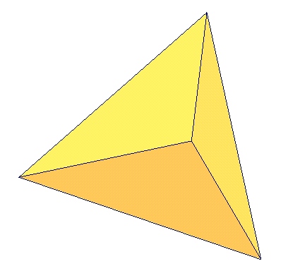
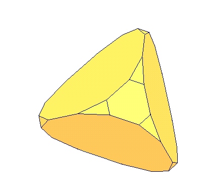
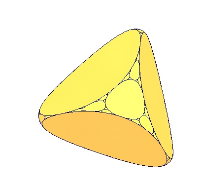
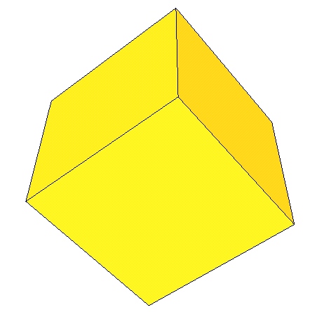
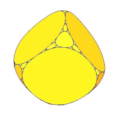
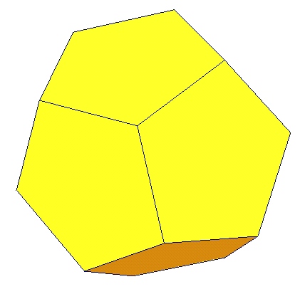
1/4 and 3/4. Figure 3 shows five iterations of this scheme
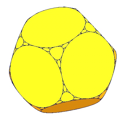
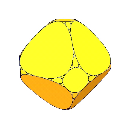
when it is applied to uniform tetrahedron. Figure 4 shows
the effect of five iterations of the scheme when it is applied to uniform
cube and dodecahedron respectively.
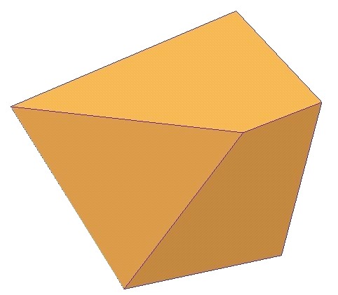
Figure 3: A tetrahedron and 5 successive vertex truncation operations applied to the tetrahedron.
created by 5 successive operation of vertex truncation. B1 is a dodecahedron and B2 is its smooth fractal counterpart created by 5 iterations of vertex truncation. Unlike polyhedral vertex truncation, with this scheme, the faces, in the limit, do not go to circles; Chaikin algorithm approaches quadratic B-splines [19,24] and parametric polynomials cannot represent circles [2]. Similar to polyhedral vertex truncation, we can show that the dimension of the edges will also be D=1.5849. Comparing to polyhedral vertex truncation, this new vertex truncation scheme has several advantages. It is stationary and simple to implement. Moreover, the scheme is robust, i.e. it can be applied to any manifold mesh. Although, the new scheme can be applied to any manifold
mesh, if each face of initial mesh is planar and each vertex is 3-valent,
then in each iteration we construct only planar faced polyhedral meshes,
which can be very useful for Architectural applications. Initial 3-valent
vertex condition guarantees that newly created faces after first application
of the vertex truncation are planar faces. But, this is not necessary condition,
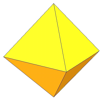
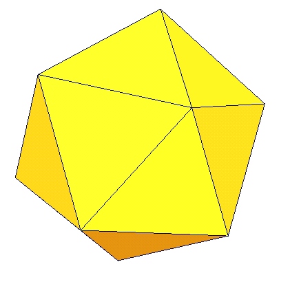
i.e. for some special planar polyhedra such as regular octahedron and icosahedron
as shown in Figure 5, the scheme still creates planar
faces even with valence other-than-3 vertices. (Since all the vertices
are 3-valent after the first iteration, each face created after second
iteration is automatically planar.) To create interesting polyhedra with
planar faces, the initial faces have to be planar, but they not have to
be uniform. They can have any shape, e.g. stars and other non-convex shapes.
The Figure 6 shows two such examples.
Figure 5: A1 is an octahedron and A2
is its 5 times vertex truncated version. B1 and B2 are an
icosahedron
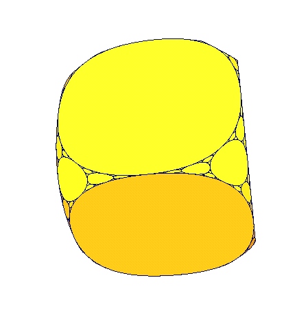
If the initial meshes do not have only planar faces and
3-valent vertices, some faces of the constructed polygonal mesh may not
be planar. The problem with such non-planar faces is that they may not
be meaningfully reconstructed during rendering process. The problem can
be theoretically worse during hardware rendering, but, as it can be seen
in the screen-shot images shown in Figure 7, these non-planar
faces with curved boundaries can be acceptably rendered (On the other hand,
one of the bilinear quadrilateral faces of the deformed cube in Figure
7 do not look like a quadrilateral because of the triangulization in
rendering stage). To build a real solid shape, the non-planar faces with
curved boundaries need to be reconstructed by using a boundary interpolating
subdivision scheme [24].
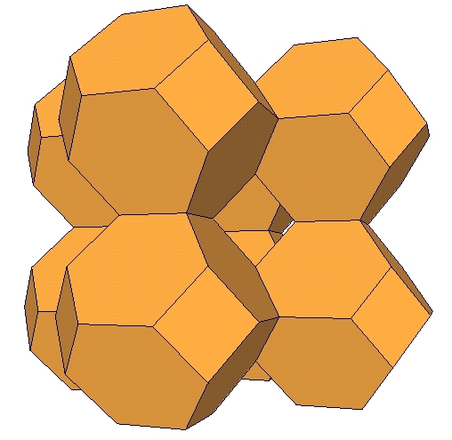
times vertex truncated counterpart. B1 is another non-convex polyhedron with non-convex planar faces and B2 is its 5 times vertex truncated version.
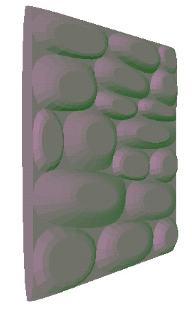
version. B1 is a genus-1 shape with 4 valent-5 vertices that cause to construct non-planar faces in the first iteration and B2 is its 4 times vertex truncated version. C1 and C2 are a shape that is created by connecting eight space-packing polyhedra, truncated octahedron, and its 4 times vertex truncated version. 4. Implementation The algorithm above is implemented and included in our existing 2-manifold mesh modeling system, TopMod, [21] as an option. Our system is implemented in C++ and OpenGL, FLTK. All the examples in this paper were created using this system. An unexpected usage of this approach is modeling walls that are made
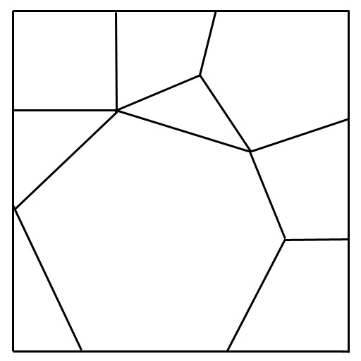
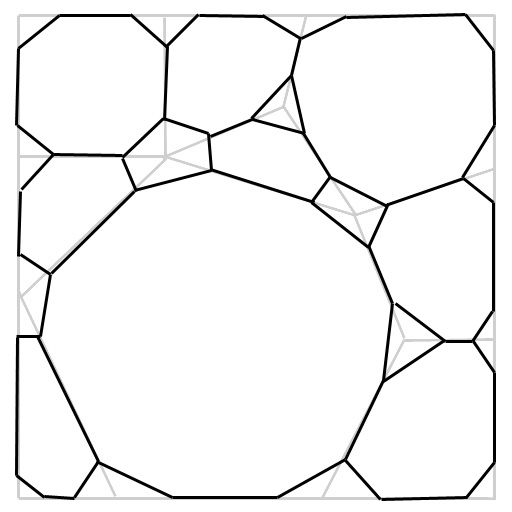
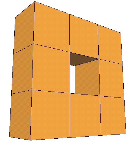
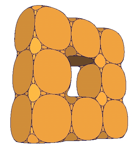
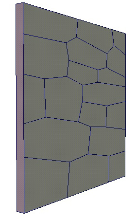
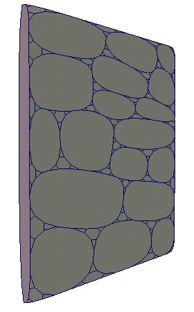
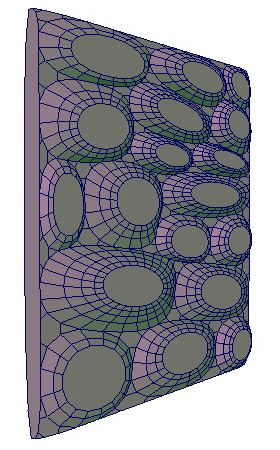
up stone as seen in Figure 8.D. To create such stone
walls, we first subdivide a planar face into a set of polygons with valence-3
vertices (see Figure 8.A) and applied a few iteration
of vertex cutting algorithm (see Figure 8.B). Then, using
standard extrusion operation, we extrude each rounded face a few times
with decreasing amount scaling and translation (see Figure
8.C).
Figure 8: A stone wall created by using our approach.
5. Conclusion In this paper, we presented a new class of polyhedra.
All the faces of these polyhedra are planes that are bounded by quadratic
B-spline
curves and the face boundaries are C1 discontinuous everywhere.
These polyhedral shapes are limit surfaces of a simple subdivision algorithm
that truncates the vertices. We obtain an approximation of these smooth
fractal polyhedra by iteratively applying this new vertex truncation scheme
to an initial manifold mesh. Our vertex truncation scheme is based on Chaikin's
construction. If the initial manifold mesh is a polyhedron only with planar
faces and 3-valent vertices, in each iteration we construct a polyhedral
mesh in which all faces are planar and every vertex is 3-valent.
6. Acknowledgments We are thankful to anonymous reviewers for their helpful
suggestions.
References [1] B. Aaron, "Violated Perfection: Architecture and the Fragmentation of the Modern'', (January 1991) Rizzoli. [2] R. H. Bartels, J. C. Beatty, and B. A. Barsky, An Introduction to Splines for use in Computer Graphics and Geometric Modeling, Morgan Kaufmann Publishers, Los Altos, CA, 1987. [3] M. Barnsley, Fractals Everywhere, Academic Press, Inc. San Diego Ca. 1988. [4] W. Bechhoefer and C. Bovill, "Fractal Analysis of Traditional Housing in Amasya, Turkey'', IASTE [International association for the study of traditional environments] Journal, Volume 61, 1995. [5] B. Carl, "Fractal Geometry in Architecture & Design'' Springer Verlag, (September 1995). [6] M. C. Escher, "The graphic works: introduced and explained by the artist'', Barnes and Nobles Books, New York, (1994). [7] H. Ferguson, webpage: www.helasculpt.com [8] G. Hart, webpage: www.georgehart.com [9] B. Grossman, webpage: www.bathsheba.com [10] L. Greg, "Das erneuerte Neue der Symmetrie,'' Arch+ number 128 (1995), Arch+ Verlag GmbH Aachen, ISSN 0587-3452, p.49. [11] B Kolarevic, "Digital Architecture'', Proceedings of Acadia'2000, Washington DC, October 2000. [12] B. Mandelbrot, The Fractal Geometry of Nature, W. H. Freeman and Co., New York, 1980. [13] L. Neal (Ed) ``Designing for a Digital World,'' Academy Editions (UK), (March 15, 2002) [14] M. J. Ostwald and R. John Moore, "Charting the Occurrence of Non-Linear Dynamical Systems into Architecture." In Simon Hayman ed. Architectural Science: Past, Present and Future.] (Sydney: Department of Architectural and Design Science, University of Sydney, 1993), 223-235 [15] M. J. Ostwald and R. J. Moore, "Fractalesque Architecture: An Analysis of the Grounds for Excluding Mies van der Rohe from the Oeuvre.'' In A. Kelly, K. Bieda, J. F. Zhu, and W. Dewanto, eds. Traditions and Modernity,] (Jakarta: Mercu Buana University, 1996), 437-453; [16] M. J. Ostwald and R. J. Moore, "Fractal Architecture: A Critical Evaluation Of Proposed Architectural And Scientific Definitions'', in Kan, W. T. ed., Architectural Science, Informatics and Design (Shan-Ti: Chinese University in Hong Kong, (1996), 137-148 [17] M. J. Ostwald "Fractal Architecture: Late Twentieth Century Connections Between Architecture and Fractal Geometry,'' Nexus Network Journal], vol. 3. No. 1. [18] G. Proctor, and J. Glymph, 2002 George Proctor with James Glymph FAIA, in ACADIA 2002 - Thresholds: Design, Research, Education and Practice, George Proctor, editor, xi - xiv. The Association for Computer Aided Design in Architecture. [19] M. Sabin, "Subdivision: Tutorial Notes'', Shape Modeling International 2001, Tutorial, May 2000. [20] C. Séquin, webpage: www.cs.berkeley.edu/~sequin/ [21] Topological mesh modeling site: www-viz.tamu.edu/faculty/ergun/topology [22] "SHoP/Sharples Holden Pasquarelli, Versioning : Evolutionary Techniques in Architecture'', Academy Editions (UK); (December 20, 2002). [23] R. Williams, The Geometrical Foundation of Natural Structures, Dover Publications, Inc., 1972. [24] D. Zorin and P. Schröder, editor, Subdivision for Modeling and Animation, ACM SIGGRAPH'2000 Course Notes no. 23, July, 2000.
|