Three-Dimensional and Dynamic Constructions
Based on Leonardo Grids
Rinus Roelofs
Sculptor
Lansinkweg 28
7553AL Hengelo, the Netherlands
E-mail: rinusroelofs@hetnet.nl
Abstract
Leonardo grids is the name I gave to my bar grid construction system with which I was able to construct domes and spheres out of simple elements using one constructing rule. Most of the constructions I made where planar and static.
In this paper I want to focus on the nonplanar and dynamic possibilities of the Leonardo grids.
1. Definition of the bar grid system
The Leonardo grid construction system is a way to make constructions using simple line shaped elements, like rods or beams. The system can be described as follows: on each element we define four connecting points, two at or near the ends and the other two somewhere in the middle at a certain distance from each other. We call these points respectively endpoints and interior points. In this kind of constructions endpoints of one rod may only be connected to midpoints of another rod and vice versa. An example can be seen in Figure 2, a dome structure also represented in the drawing by Leonardo da Vinci in Figure 1 at the left. The drawing of the stucture (Figure 3), which we shall call a Leonardo grid, can be seen as a graph. And this graph has the property that every vertex has degree 3. For the domes the representing graph is always a planar graph. The name Leonardo grid was chosen because his drawings are the only references I found.
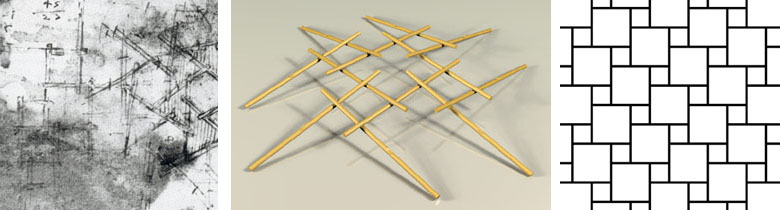
Figure 1:
Drawing by L. da Vinci. Figure 2: Dome construction. Figure 3: Graph.
2. From 2D to 3D
Also the spheres built with the Leonardo grid construction system can be represented by a planar graph. So in fact the sphere is a 2D object. It is no more than a bent surface. In the example (Figure 4) you can see that the elements don't have to be straight sticks. The four connecting points and the connection rule can be recognized in the model, of which the graph is presented in Figure 5. I found many patterns that can be used as Leonardo grids and all these patterns can be used as basic designs for domes and spheres.
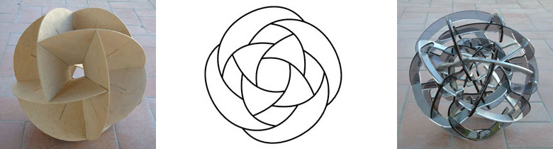
Figure 4:
Sphere - 12 elements. Figure 5: Graph. Figure 6: Sphere in sphere.
The question arose whether it would be possible to make real 3D constructions based on the Leonardo grids. Is it possible to make multi layer objects using the Leonardo grids? Or even can we make 3D space frames built out of simple elements just like in the domes? So mathematically speaking instead of planar graphs I had to look for non-planar graphs now.
A first example of a real 3D construction is the double sphere in Figure 6. In this object you can see a sphere within a sphere. Each of the 24 elements is half in the inner sphere and half in the outer sphere. The design was made by starting with two layers of Leonardo grids. The layers were placed above each other in such a way that after cutting each element in two parts, half elements from the upper layer could be connected to half elements of the under layer. The resulting structure again has all the properties needed for a Leonardo grid: each element is connected to 4 other elements in the right way: all endpoint connected to midpoints and all midpoints connected to endpoints. Half of the connecting points are on the surface of the inner sphere, the other half on the surface of the outer sphere. A first non-planar or real 3D result. And surprisingly enough the total structure appeared to be stable.
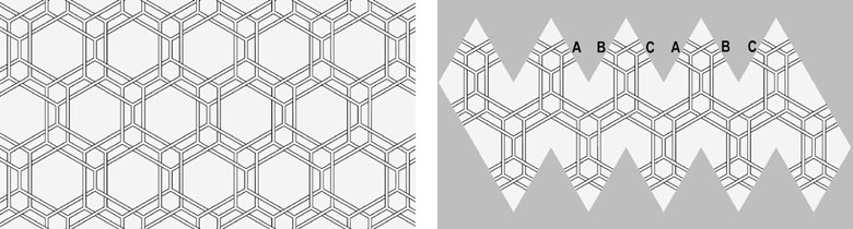
Figure 7:
Three interwoven patterns. Figure 8: Icosaherdon - plan.
Another approach is to start with interwoven patterns (Figure 7). A simple way to transform a flat pattern into a spherical construction is to use a polyhedron. When the pattern is hexagonal, the net of a icosahedron can be used. In the special case of the three interwoven patterns of Figure 8 the cut off elements of pattern A will be connected to the cut off elements of pattern B when folding the net to an icosahedron. And so with the cut off elements of B and C and of C and A.
The result is real 3D Leonardo grid construction. And now all the connecting points are laying in the same spherical surface. In the pictures (Figure 9, 10 and 11) you can see some variations.
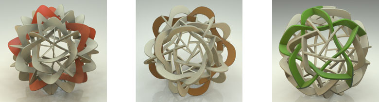
Figure 9:
Interwoven sphere - A. Figure 10: Interwoven sphere - B. Figure 11: Interwoven sphere - C
Although this is a good approach it is hard to find a good set of interwoven patterns that can be used for this method.
3. Infinite double layer structures
To go one step further towards the Leonardo grid space frames I first tried to find a way to construct infinite double layer structures. Space frames can be built by connecting polyhedra in systematic way. Cubes stack so as to fill space completely. And when you look at the graph that represents the cube you will notice that all vertices have degree 3, which was a condition for the Leonardo grids. A cubic frame can be made as a Leonardo grid construction in three different ways (Figures 12, 13 and 14; only in Figure 14 the ends point to the X, Y and Z-direction).
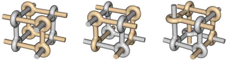
Figure 12:
Cubic frame - A. Figure 13: Cubic frame - B. Figure 14: Cubic frame - C
A way to make a double layer structure is to connect these kinds of cubes as in Figure 15. This will result in a non-planar infinite construction that has also dynamic properties. The elements can slide between certain boundaries and the total construction can be pressed together or stretched.
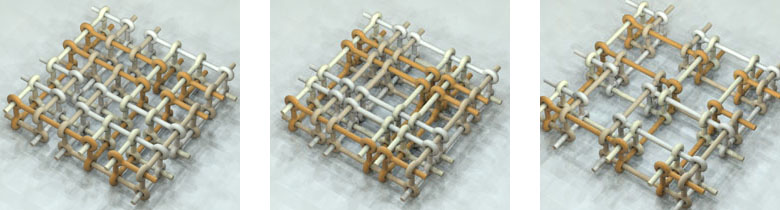
Figure 15:
Double layer structure Figure 16: Pressed together. Figure 17: Stretched
4. Rings and strings
In the double layer structures the basic elements, the rods with the 4 connecting points, are linked together to form bigger units. We can distinguish two kinds of these bigger units: rings, a closed concatenation of a finite number of basic elements, and strings a (open) concatenation of an infinite number of basic elements. Some examples of both categories are shown in Figures 18, 19 and 20 (rings) and Figures 21, 22 and 23 (strings).
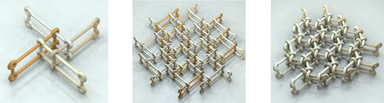
Figure 18:
Double layer structure Figure 19: Pressed together. Figure 20: Stretched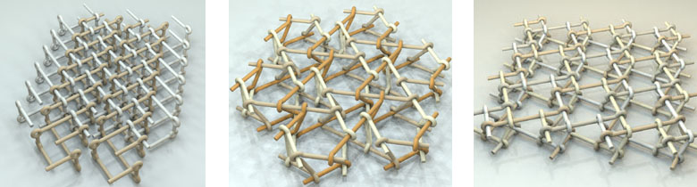
Figure 21:
Double layer structure Figure 22: Pressed together. Figure 23: StretchedAnd the constructions don't have to be limited to 2 layers as can be seen in Figures 24, 25 and 26. Here an infinite 3D construction is built with one type of string, which is a concatenation of basic Leonardo grid elements.
The question still is whether it is possible to make space frame constructions out of basic elements which are not linked.
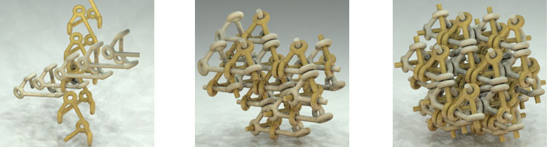
Figure 24:
Strings 3D Figure 25: String structure 3D. Figure 26: String structure 3D
5. Grid transformation
Another, and perhaps even better way to construct real 3D structures based on Leonardo grids appeared to be the use of transformation of the basic Leonardo grid from 2D to 3D. The process can be described as follows: we can start with any pattern in which we can find a hexagonal hole. We now keep the 6 sticks around this hole connected and change the hexagon from flat to skew. This change will cause a transformation of the sticks, which are connected to the first 6 sticks. The six parallelogram shaped holes in the pattern will also be parallelogram shaped at the end of the process. But one of the connections around the triangle holes will get loose. The resulting structure now can be used as a layer with which we can create space frames.
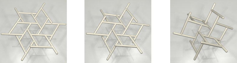
Figure 27:
Leonardo grid 2D. Figure 28: Halfway between . Figure 29: Leonardo grid 3D.The discovery of this process lead to many designs of Leonardo grid space frames because the process could be applied on all the flat basic patterns. We can also start with a square hole in a pattern. In the same way the flat hexagon is transformed into a skew hexagon, a flat square can be transformed into a skew square. The over a hundred different patterns that I had drawn as possible designs for the domes can now be transformed to Leonardo grid space frames. In the illustrations you can see some examples of the resulting space frames.
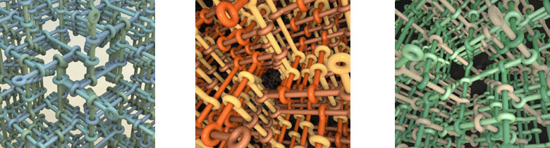
Figure 30:
Space frame grid A Figure 31: Space frame grid B. Figure 32: Space frame grid C.
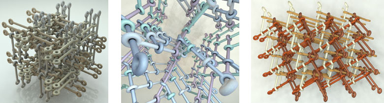
Figure 33:
Space frame grid D Figure 34: Space frame grid E. Figure 35: Space frame grid F.
6. Dynamic space frames
Just as in the double layer structures the Leonardo grid space frames also have dynamic properties.The sticks can be slid along each other and so the total construction can be pressed together or stretched. To show this we will go back to the skew hexagon first. In Figures 36, 37 and 38 you see three stages of the sliding process. And we can extend that to a complete layer as in Figures 39, 40 and 41. In the total movement it looks as if there is some twist in the structure. The shrinking and growing of the structure is in a way a spiral movement. This can be best viewed in animation.
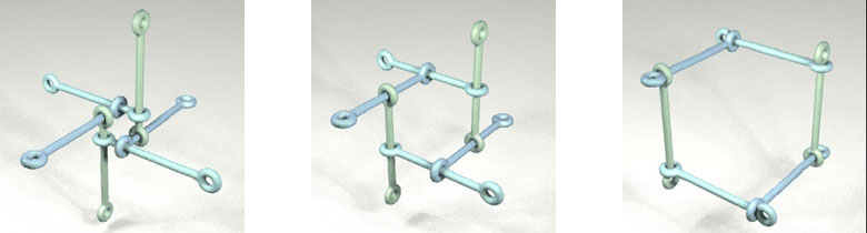
Figure 36:
Sliding first stage. Figure 37: Sliding second stage. Figure 38: Sliding third stage.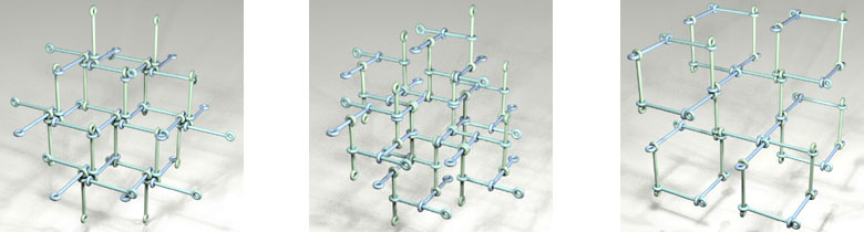
Figure 39:
Sliding first stage. Figure 40: Sliding second stage. Figure 41: Sliding third stage .
7. Dynamics in 2D
While studying dynamics in the 3D Leonardo grid constructions I also discovered an interesting new way of translating 2D Leonardo grids into dynamic structures. Looking again at the basic grids you will realize that there are two possible interpretations: you can either look at it as a construction built out of rods or as a tiling, a pattern built with a set of tiles. The dividing lines then form the Leonardo grid.
One line in this grid represents the edges of 4 tiles: 2 big tiles and 2 small tiles. So this one gridline can be seen as a set of 4 edges. And because the edges are alternating long-short-long-short, the set of edges can be seen as a collapsed parallelogram. In the original grid the tiles are close to each other so the described has area zero. But what will happen when we 'open' the parallelogram? The set of tiles then turn out to be a dynamic hinged construction. The Leonardo grid lines transform from line to parallelogram to rectangle and back via parallelogram to Leonardo grid line again. And as a result of this process is that a left-hand orientation of the Leonardo grid has changed into a right-hand orientation.
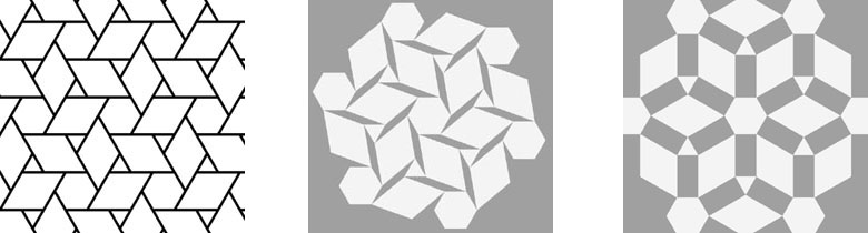
Figure 42:
Transforming first stage. Figure 43: Second stage. Figure 44: Third stage.And because this process can be applied on any Leonardo grid this lead to an enormous collection of hinged tile constructions. Most special is that this process also works on Leonardo grids with distortions, Leonardo grids in which more than one pattern is used, and on Leonardo grids in which more than one length of grid lines is used. Some examples can be seen in the figures.
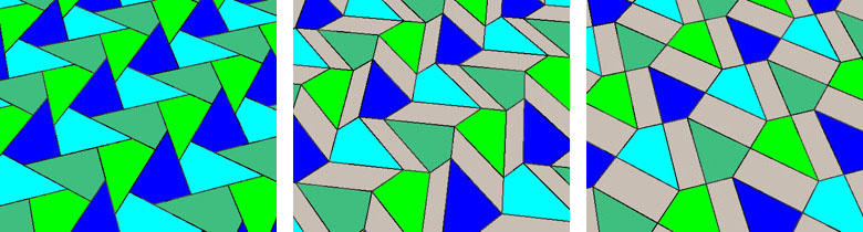
Figure 45:
Transforming first stage. Figure 46: Second stage. Figure 47: Third stage.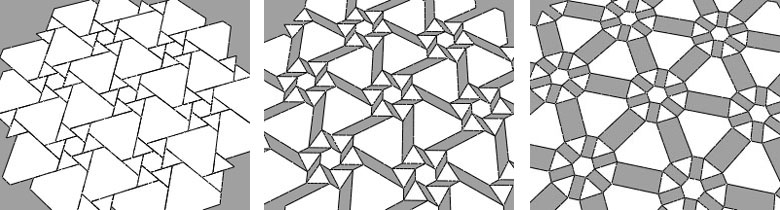
Figure 48:
Transforming first stage. Figure 49: Second stage. Figure 50: Third stage.Of course this can be better viewed in animation.