|
A Salamander Sculpture Barn Raising George W. Hart Computer Science Department. Stony Brook University Stony Brook, NY 11794-4400, USA E-mail: george@georgehart.com
Abstract
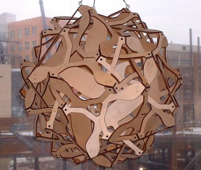
1. Introduction M.C. Escher playfully incorporated chameleons and other reptiles or amphibians in his two-dimensional geometric artwork [1]. In homage to his creative spirit, I designed my sculpture Salamanders to feature flat salamanders which interweave in three dimensions. Figure 1 shows it hanging temporarily inside a window overlooking the construction of Frank O. Gehrys new Stata Center at M.I.T. [2], where the sculpture will eventually reside.
Figure 1: Salamanders My ultimate concept, if funding can be found, is for a large metal double sphere as shown in Figure 2. The inner and outer spheres are each made of thirty identical two-headed salamander shapes. Each part is parallel to an identical part similarly oriented in the other sphere. I find it visually interesting to show that the same salamander parts can be joined in these two contrasting arrangementsone very open and one very interlocked. It is a puzzle with two very different solutions. The outer sphere of Figure 2 does not present any inordinate construction challenges. I am certain that I can fabricate its thirty components and assemble them. The inner sphere was my fundamental concern. From a computer rendering such as Figure 3, I can verify that there exists a configuration in which the parts do not intersect each other in the interior, yet exactly meet edge-to-edge along the exterior. However there is no mathematical method to determine if the thirty initially separate rigid components of this sculpture can be physically manipulated to weave them into the desired configuration. What is the assembly algorithm? Notice that one could not simply position pieces one at a time, because if one tried to insert the last piece after all the others are positioned, the legs would block access. The two hands of one sculptor are not sufficient to manipulate so many components simultaneously, so this was an ideal question for the collective creativity of a group assembly project. I have led other sculpture "barn raisings" [4], but for them I had a proven assembly algorithm pre-designed. When I was invited to be artist in residence at MIT [6], this thirty-component assembly project struck me as an ideal group activity to try there.
Figure 2: Salamanders,
concentric spheres concept.
Figure 3: Inner sphere of Figure 2.
2. Design Although geometric and salamander-filled, in most ways this work involves very different design problems than Eschers art, because these parts interweave in three dimensions. Both spheres of Figure 2 fall within a large family of geometric sculptures I have been exploring [5], based on symmetrically arranged planar components. Physically, these works consist of interwoven identical components that can be accurately laser cut, delivered flat to the assembly site, then woven through each other on-site and fastened together. Mathematically, the design of these sculptures involves drawing within the "stellation diagrams" of polyhedra. Other software exists for creating stellated polyhedra [9], but my approach [5] is unique in allowing design and visualization of free-form drawings within the stellation planes. Stylistically, this allows me to create an Escher-like sense of structured confusion. For Salamanders, the underlying polyhedron is the rhombic triacontahedron (RT), which consists of thirty "golden rhombi," arranged with icosahedral symmetry, as shown in Figure 4. When the thirty face planes of the RT are extended to infinity, the pattern of their intersection in any one of the planes is a set of lines partly visible in Figure 5. Superimposed over these lines is the shape I drew for the salamander part. The dark lines are to be laser cut and the light inner lines indicate how the area is divided into triangles.
Figure 4: Rhombic triacontahedron (30 rhombi)
Figure 5: Salamander layout in RT stellation diagram If made in metal plate, I would design tabs with holes attached to the feet, folded to the proper dihedral angle. Dotted lines in Figure 6 show how two foot tabs could connect on the back of the head. Round-head bolts with hexagonal sockets would be used to hold everything together and also serve as eyes. However, for joining the wood components, I pre-made sixty small wood connectors, miter-cut at the appropriate face angles and dihedral angles. The feet screw into a connector glued behind each head.
Figure 6: Design with bolts for eyes
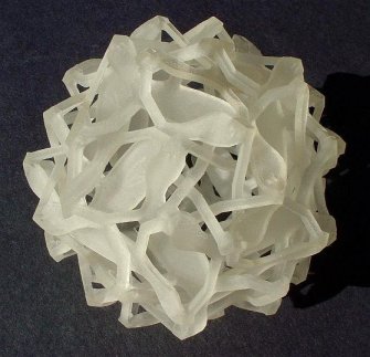
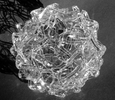
Figure 7: Solid freeform fabrication model A 3D model of the form is shown in Figure 7. It is a 2.5 inch diameter model made on a Stratasys/Objet Eden 333 machine. The .stl file that describes its geometry is available at my web site for anyone with solid freeform fabrication equipment who wishes to make a copy [3]. Such models are assembled in thin cross-sectional layers on a 3D printing machine, so they give a visual and tactile sense of the structure. But they do not demonstrate whether the form could be assembled from rigid planar components. I was afraid to put myself in the embarrassing position of creating thirty large parts and bringing a crew of thirty people together only to find out my design was impossible to assemble. So I made a seven-inch prototype in rigid acrylic plastic (Plexiglas), to verify that the parts can be woven without jamming together. Before I had thirty four parts cut, I had to lay them out for the 24 inch square working area of a laser cutting service. Interestingly, the parts pack together quite tightly, minimizing material wastage, as seen in Figure 8. It took half a day to assemble the plastic parts. By wiggling parts slightly to open small spaces which let other parts be inserted, all the while holding everything loosely together with many fingers, bits of tape, and small rubber bands, eventually I managed to get the last piece in place. So I had an existence proof that assembly was possible, but I certainly did not have anything like a well-defined assembly algorithm. The resulting model, after gluing the parts, is shown in Figure 9. Because it is clear, it may difficult to determine what is what in that photo, but I can attest that in person it is quite cool looking.
Figure 9: Plexiglas model, 7 inches
3. Sculpture Barn Raising When the time came for my residency at MIT, I brought the acrylic model and the 3D printing model with me to show people what we would be building at the group assembly event. I am very grateful to my host Erik Demaine, and also to Marty Demaine and Abhi Shelat, all of whom spent many hours with me on the preparations. In the days there before the assembly, we used a laser cutter to cut the thirty wood salamanders (and some spares). The wood we finally selected is a Baltic birch plywood, laser-engraved with ovals for the eyes, then sanded, drilled and countersunk in four places for screws, glued to two mitered wood junction pieces, and given a protective coating of tung oil. We also made a large quantity of scaled-down paper salamanders for practice assembly. One important lesson we learned late along the way is not to purchase large amounts of expensive ash plywood of a type which chars into embers when one tries to laser-cut it. If you want to make your own paper or wood model, Figure
10 is an image of how we laid out a pair of parts in the 32-by-18 inch
bed of the laser cutter we used. Even without a laser-cutter, you can make
thirty copies (enlarged) on card stock, cut them out with scissors, and
assemble your own paper model.
Figure 10: Layout for cutting wooden
parts
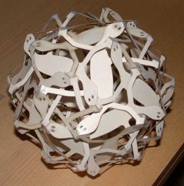
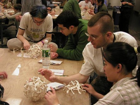
Figure 11: Taped together paper model On the day of assembly, roughly fifty volunteers started work around four large tables in one of the studio art rooms. Everyone received an envelope with thirty laser-cut paper salamanders. After some instruction on how the parts go together, and by studying the models I brought, we began individually or in small groups to assemble. Figure 11 shows one of the paper models. Figure 12 shows its construction. Small pieces of clear tape hold a long leg, a short leg, and a head at each of the sixty junctions. It is important to understand that the two-headed salamanders can have their heads all facing to the left or all facing to the right, and that each salamander is part of two different types of pentagonal cycles.
Figure 12: Working on the paper models It is initially tricky to master how the parts weave through each other, and internalize what should be inside and what should be outside. The long legs which make a star pattern at the five-fold junctions are the biggest problem. The "ankle" of each long leg must be outside of the "knee" of the leg it crosses. Paper is flexible, allowing legs to be bent around each other and into place. But the real challenge for everyone was to design an assembly strategy which would later work with rigid wooden components. After an hour and fifteen minutes of paper practice, I felt that enough people understood the structure. We then started on the real assembly of the wooden parts.
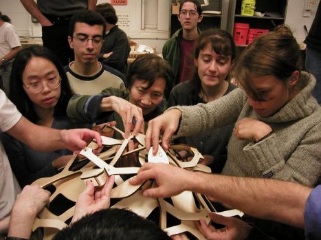
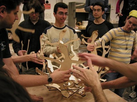
Figure 13: Starting the assembly of the wooden salamanders
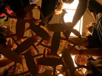
Figure 14: Looking up into the first cap of ten salamanders. After some discussion, the assembly method
we chose was based on three units of ten salamanders each: two polar caps
and an equator. Figure 13 shows the initial step, working
in the air with five parts around an imagined vertical five-fold symmetry
axis. Then another five parts weave into those, making the first cap of
ten parts. Figure 14 is a view from below looking up
into the first cap being assembled. It was loosely screwed together, and
then put aside. A second cap was assembled in the same manner. Our strategy
was to make an equator of the remaining ten parts to connect the top and
bottom caps.
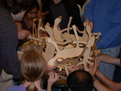
Figure 15: Adding the equator to the bottom ring.
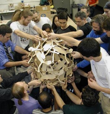
Figure 16: Finishing the equator We did the final assembly by placing one cap facing up on the table and first adding an equatorial ring of five salamanders whose bodies are aligned vertically, as seen in Figure 15. Then we wove in the overlapping equatorial ring of five salamanders whose bodies are aligned more horizontally, shown in Figure 16. (Each salamander is part of one ring of each type; each five-fold equator is made of both types of ring, concentrically arranged but not contacting each other.) Finally, the other cap was lowered on to the top, as shown in Figure 17. This last step took some time and a number of retries to get the legs properly interwoven.
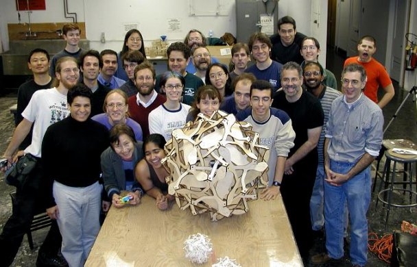
Figure 17: Adding the top cap Everything worked out, so the remaining screws could be inserted and all 120 screws were tightened. The final result is in Figure 18. I found it to be surprisingly rigid for its 15 pounds of weight. The total time for the assembly of the wooden parts was one hour and forty minutes.
Figure 18: Finished!
4. Conclusion I consider the Salamanders barn raising to have been a great success. I am very happy with the final sculpture and the wonderful preparation and assembly support that I received at MIT. Many more photos plus short digitized videos of the assembly are available online [7]. The work has been selected as the first in the art collection of the MIT Computer Science and Artificial Intelligence Laboratory. Our plan for its future is that it will hang in the new Stata center. After it is moved to its public location, I hope Salamanders will remind viewers of the beauty of geometry and the tradition of M.C. Escher. References [1] M.C. Escher, Bruno Ernst, The Magic Mirror of M.C. Escher, Ballantine, 1976. [2] Frank O. Gehry, Stata Center, http://web.mit.edu/evolving/projects/stata/ [3] George W. Hart, web pages, http://www.georgehart.com [4] G. Hart, "The Millennium Bookball," Proceedings of Bridges 2000: Mathematical Connections in Art, Music and Science, Southwestern College, Winfield, Kansas, July 28-30, 2000, and in Visual Mathematics 2(3) 2000. [5] G. Hart, "Sculpture from Symmetrically Arranged Planar Components", in Meeting Alhambra, (Proceedings of ISAMA-Bridges 2003, Granada, Spain), Javier Barrallo et al editors, Univ. of Granada, 2003, pp. 315-322. [6] MIT artist-in-residence program, http://web.mit.edu/arts/special_programs/air/index.html [7] MIT page of photos and videos, http://theory.lcs.mit.edu/GeorgeHart/residence_101103.htm [8] MIT Tech Talk articles, http://web.mit.edu/newsoffice/tt/2003/nov19/salamander.html [9] R. Webb, "Stella: Polyhedron Navigator," Symmetry
Culture and Science, 11, No. 1-4, pp. 231-268, 2000/2003.
Acknowledgments I thank the many people at MIT who made this project possible. First and foremost, Erik Demaine invited me to be artist-in-residence through the Office for the Arts and the EECS department. Erik Demaine, Marty Demaine, and Abhi Shelat spent many hours with me doing the preparations, especially laser-cutting the wood and paper. Rebecca Frankel helped with the oil finish. The CSAIL fabrication shop and staff provided the laser-cutter and other resources. Erik Demaine, Mark Hoffman, and Moses Liskov took many photos, including the ones in this paper. Tom Buehler from the CSAIL Computer Graphics group took and edited video. Michele Oshima, Nicole Ackerman, and Marc Rios at the MIT office for the Arts did advertisement and behind-the-scenes logistic arrangements. Tech Talk ran nice articles which helped draw a crowd to the event and report the results [8]. And of course, my thanks most of all go to each of the barn raisers who came and participated in the assembly.
|