|
THE WORLD OF SCIENTIFIC PUZZLE ART USING LAYER MANUFACTURING
Yasunari Watanabe(1), (2), (3), Yuji Ikegami (2), (3), Kenji Yamazawa(2) and Yoshiko Murakami(1) Addresses: (1) Department of Information, Teikyoheisei University, Ichihara Chiba 290-0193 Japan, (2) Institute of Physical and Chemical Research, Wako Saitama 351-0198 Japan, (3) Interdisciplinary Institute of Science, Technology and Art, ISTA, Kitahara 2-10-6 Asaka Saitama 351-0036 Japan
Introduction Advances of the techniques of layer manufacturing are remarkable and the field of their application is expanded to not only mechanical engineering but also artistic work (Y. Yoshihara, 2002). We tried to build two kinds of geometrical/artistic three dimensional (3D) models as follows using two layer manufacturing systems, laser lithography or powder layer manufacturing (Y. Watanabe and Y. Ikegami, 2002). 3D Escher pattern depending on periodic structure of crystals and 3D jigsaw puzzle of which sliding system is hinted from Japanese carpenter’s techniques. It is introduced that layer manufacturing technique play an important role in interdisciplinary field of science and art. 1 Principle of layer manufacturing Molding system by slicing and stacking the 3D CAD data of the objects is called rapid prototyping. There are two processing methods to build the mold, Laser lithography and powder layer manufacturing. Resin hardened by laser beam for the former and print assembly by the binder solution for the latter is used as a building material of the objects respectively. Molding basic process in the both methods generating 3D Escher pattern or 3D jigsaw puzzle is as follows: (1) Data of 3D model is generated using CAD system and transformed into standard STL (Stereo Lithography) data that is represented by triangle patch. (2) STL data is processed to generate a data of many cross sections, which are sliced according to the stacking pitch. Scanning pattern of the supporter for overhanging, scanning speed of laser beam and position of the objects etc. are set up and sent to molding machine. (3) Scanning laser beam along to slice data of the objects, irradiated region of liquid resin harden to be thin film. Cross section pattern followed by slice data is obtained.(4) Elevator stage on which hardening objects are mounted move downwards by amount of slice pitch.(5) Recoating liquid surface of resin, new thin liquid layer is generated automatically on the hardened resin layer. (6) (3), (4), (5) processes are iterated until objects are built. After all processes finish pull up elevator and take out the object.
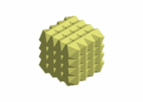
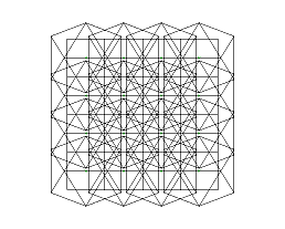
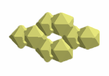
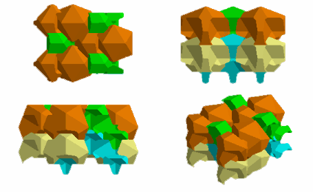
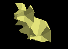
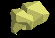
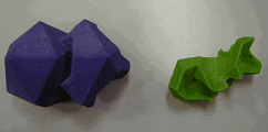
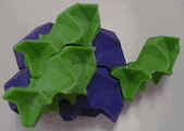
2 Solidification of 3-dimensional Escher Pattern Powder layer manufacturing machine, COSMART-I, builds 3D Escher Patterns. Two types of solid model are presented, whose original data are designed using CADPAC2 software. In the preparation of the model building an icosahedron is considered as a basic unit of the modeling, which is an isotropic polyhedron with the maximum facet in the regular-polyhedrons. Several inscribed cubes in the icosahedrons can be arranged such that they form cubic lattice decorated by set of icosahedrons. Assembled icosahedrons are formed to be 3D periodic structure with overlapped region of the icosahedrons inside and icosahedrons facet outside of the assembly (Fig. 2-2). 3D Escher model building begins with the deformation of unit cell of the cubic lattice by iterative arithmetic operation of CAD system. External of icosahedrons is much available for creating the body of animals, which has mirror symmetry. First, cut two vertices in the icosahedrons assembly into a nose, ears and back of an appearance of an elephant as shown in Fig. 2-3 Secondly, take out remainder or complementary set of elephant set from icosahedrons assembly as shown in Fig. 2-4. Third, cut unit cell of the remainder into other animal shape. The third processing is so difficult that divided solid model cannot look like something of animal. Iterate operations of first, second, third, first, second, third are continued until an animal pattern appear. Consequently, the character of solid models obtained is represented by one set of animals, elephant and frilled lizard (Fig. 2-5 and Fig. 2-6). Packing pattern and its product are shown in Fig 2-7 and Fig. 2-8.
Fig. 2-1 Wire frame of icosahedrons
Fig. 2-2 Shading of icosahedrons assembly
Fig. 2-3 Elephant set built by icosahedron’s pair
Fig. 2-4 Complementary set obtained from icosahedron’s assembly
Fig. 2-7 Packing projection: Plan (upper left), Front
view (upper right),
Fig. 2-5 Frilled lizard
Fig. 2-6 Elephant
Fig. 2-8 Packing of product
Fig. 2-9 Product of Elephant and frilled lizard 3 3D jigsaw puzzle
Fig. 3-1 Single layer jigsaw
Fig. 3-2 Cubic jigsaw
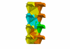
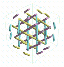
Fig. 3-3 Orbit around puzzle [111] screw axis Jigsaw puzzle is one of the most popular puzzles. However, Authors developed a single-layer jigsaw puzzle as shown in Fig 3-1. It seems that any piece could be slid neither up-wards nor down-wards, and neither front-wards nor backwards. But each piece can be separated into nine blocks. Consider a new 3D jigsaw puzzle with 3×3×3=27 pieces as shown in Fig. 3-2. This puzzle has multi-layer structure. It seems that every pieces cannot be slid in x-y, y-z, and z-x surface as well as in the single layer case. How to slide the each piece and take it apart. The problem is solved by considering the geometry of orbit on which pieces of the puzzle slide. The orbits take parallel positions each other around the screw axes of diagonal directions, that is, cubic [111], [-111], [1-11], [11-1] and their inversion. Sliding system is shown in Fig. 3-3 using rod notation representing the orbits of sliding pieces. This is an application of dovetail joint in Japanese traditional carpenter techniques. It is very interesting that the structure of rod notation corresponds to three axis rod structure model (Teshima, Y. et al. 2001) and that there exists the compound corresponding to the three axis structure of rod (O’Keeffe, M. et al. 1977). * Hayao Nakayama Foundation supports this work for Science & Technology
and Culture.
3 REFERENCES Watanabe, Y. and Ikegami, Y. (2002) The world of scientific art using layer manufacturing method, [in Japanese], Proceedings of 23rd Rapid Prototype Symposium, 105-107. Teshima, Y., Watanabe, Y., and Ogawa, T. (2002) A new structure of cylinder packing, Lecture Notes in Computer Science, LNCS-2098, Springer, 351-361. O’Keeffe, M. and Anderson, S. (1977) Rod packing and crystal
chemistry, Acta Crys., A33, 914-923.
|
