A Penrose-type Islamic Interlacing Pattern
1 Introduction
We first explain what is meant by a Penrose-type pattern, and we show
how to create a Penrose-type interlacing pattern using just five
shapes of tile - a pentagon, a 10-gon, an 8-gon that is always flanked
by two attendant small kites to form a rhombus, and a star having ten
small kites at its points (Figure 1). Then we describe how the
computer drawings shown in this article were made.
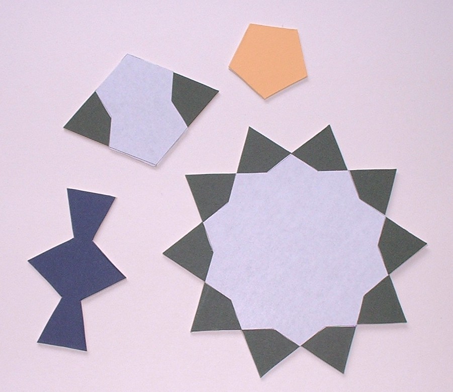 Figure 1: Basic shapes
The computer drawings, and the cardboard tiles photographed in
Figures 1 and 4, were made by Brian
Wichmann. The original patterns were created by John Rigby.
A Penrose tiling is a tiling of the plane by two types of tile, called
kites and darts [1]. The simple and obvious ways of fitting
kites and darts together are precluded by simple rules governing the
construction of Penrose tilings -kites and darts must only be fitted
together in the approved manner, as described in [1]. An
example of part of a Penrose tiling is shown in
Figure 2 (we explain the numbers added later).
Penrose tilings are aperiodic and they have other properties described
in [1].
Figure 1: Basic shapes
The computer drawings, and the cardboard tiles photographed in
Figures 1 and 4, were made by Brian
Wichmann. The original patterns were created by John Rigby.
A Penrose tiling is a tiling of the plane by two types of tile, called
kites and darts [1]. The simple and obvious ways of fitting
kites and darts together are precluded by simple rules governing the
construction of Penrose tilings -kites and darts must only be fitted
together in the approved manner, as described in [1]. An
example of part of a Penrose tiling is shown in
Figure 2 (we explain the numbers added later).
Penrose tilings are aperiodic and they have other properties described
in [1].
 Figure 2: Penrose tiling from [1]
There are two ways (which can be combined) of creating a pattern
using tiles - either we put together tiles of various shapes and
sizes, each tile having a single colour, or we superimpose a partial
pattern on a simple shape of tile - often a square but sometimes a
rectangle or hexagon or other shape - then fit together copies of
this simple tile; the partial patterns then fit together nicely (if
they have been carefully designed) to create an overall pattern. We
shall concentrate on the second method. To avoid confusion, it is
important to distinguish between the pattern made up from all the
superimposed partial patterns, and the pattern formed by the
underlying tiles (a pattern of squares, rectangles, hexagons etc.)
Let us superimpose a partial pattern on the kites and darts of a
Penrose tiling - the same pattern on each kite, and the same on each
dart. When we fit together the kites and darts to form a Penrose
tiling, the superimposed partial patterns form a basic Penrose-type
pattern [2].
The superimposed pattern that we shall create here is itself a tiling
- hence the possibility of confusion (mentioned earlier) between the tiling formed from
the superimposed partial patterns and the pattern formed by the
underling Penrose tiling! Our partial patterns are shown in
Figure 3, and the Penrose tiling - or that part of it that
we shall be using - in Figure 2. At each corner
of a kite or dart in Figure 3, there is a sector of a star,
and along each long edge there lies half a rhombus. When the
patterned kites and darts are fitted together, complete stars and
rhombuses are formed, as in Figure 4, and the final
result is shown in Figures 9 and 10.
Figure 2: Penrose tiling from [1]
There are two ways (which can be combined) of creating a pattern
using tiles - either we put together tiles of various shapes and
sizes, each tile having a single colour, or we superimpose a partial
pattern on a simple shape of tile - often a square but sometimes a
rectangle or hexagon or other shape - then fit together copies of
this simple tile; the partial patterns then fit together nicely (if
they have been carefully designed) to create an overall pattern. We
shall concentrate on the second method. To avoid confusion, it is
important to distinguish between the pattern made up from all the
superimposed partial patterns, and the pattern formed by the
underlying tiles (a pattern of squares, rectangles, hexagons etc.)
Let us superimpose a partial pattern on the kites and darts of a
Penrose tiling - the same pattern on each kite, and the same on each
dart. When we fit together the kites and darts to form a Penrose
tiling, the superimposed partial patterns form a basic Penrose-type
pattern [2].
The superimposed pattern that we shall create here is itself a tiling
- hence the possibility of confusion (mentioned earlier) between the tiling formed from
the superimposed partial patterns and the pattern formed by the
underling Penrose tiling! Our partial patterns are shown in
Figure 3, and the Penrose tiling - or that part of it that
we shall be using - in Figure 2. At each corner
of a kite or dart in Figure 3, there is a sector of a star,
and along each long edge there lies half a rhombus. When the
patterned kites and darts are fitted together, complete stars and
rhombuses are formed, as in Figure 4, and the final
result is shown in Figures 9 and 10.
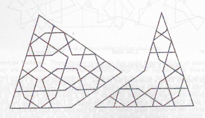 Figure 3: A patterned kite and dart
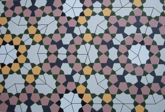 Figure 4: A basic Penrose-type pattern
We describe this pattern as an interlacing pattern because the edges
between the small tiles can be replaced by a braid; at each vertex of
the superimposed pattern two portions of braid cross each other, and
these crossings can be made in an alternate over-and-under manner
(Figure 11). The pattern is Islamic, or at least
Islamic-style, because these shapes of tile occur frequently in
Islamic patterns [2,4].
Ways of converting this pattern into more elaborate Penrose-type
Islamic patterns are described in [2], Many periodic
patterns created from the same shapes of tile can be found in
[4].
Figure 4: A basic Penrose-type pattern
We describe this pattern as an interlacing pattern because the edges
between the small tiles can be replaced by a braid; at each vertex of
the superimposed pattern two portions of braid cross each other, and
these crossings can be made in an alternate over-and-under manner
(Figure 11). The pattern is Islamic, or at least
Islamic-style, because these shapes of tile occur frequently in
Islamic patterns [2,4].
Ways of converting this pattern into more elaborate Penrose-type
Islamic patterns are described in [2], Many periodic
patterns created from the same shapes of tile can be found in
[4].
2 Construction by computer
One method of constructing specific tiling patterns is to write a
special program for the purpose. For a Penrose tiling, a simple
recursive program can be used. (Sometimes the word `substitution' is
used instead of recursion; but recursion is the computer technique
used.) Such a program can only produce Penrose tilings, Here, we
show how a more general program can be used. The program was
originally designed to draw and catalogue more than 4,000 tilings in
[3].
If we start with the existing program we find that there are three
significant problems. Firstly, the program uses local connection
rules to draw a tiling, but this will not work with a true Penrose
tiling. Instead, only a local patch can be produced. However, the
local patch can be big enough for our purposes, since if we start with
a portion of tiling that is too large, this results in individual
kites and darts which are too small to appreciate visually.
Another significant problem is that of rounding error. The drawing
program places the individual tiles on the drawing area by matching
edges. The matching needs to determine whether two points on the
plane are `equal' given the inevitable rounding errors.
Unfortunately, the rounding errors are bound to accumulate as the
number of tiles grows. With over 6,000 tiles in the largest Penrose
pattern that we have drawn, we must use double length floating point
and calculate the basic tile data to that same precision.
The last significant problem is to handle the 6,000 tiles without
having to specify in detail each tile. This is done by regarding each
kite or dart as an individual `tile' even though they are themselves
made up of tiles.
In Figures 5 to 8, the straight edges of the
kite and dart in Figure 3 have been modified in such a way
that the modified shapes fit together only in the approved manner
(compare Figure 10.3.12 of [1]). The edge numbering is
required in order to indicate how the edges fit together.
 Figure 5: Modified kite, showing edges
 Figure 6: Modified kite in colour
 Figure 7: Modified dart, showing edges
 Figure 8: Modified dart in colour
In the modified kite and dart we have got rid of the half-tiles along
the edges, but it is still necessary to use sectors of stars at the
vertices.
The strategy is to start with the recursively produced dart and kite
pattern shown in Figure 10.3.20 of [1]. This appears here as
Figure 2, with the numbers of the individual kites
and darts added. These numbers are used to determine how each kite
and dart fits with its neighbours.
Note that the number of kites and darts required is reduced by factor
of 5 due to the c5 symmetry. This reduces the work required
substantially.
The final result of this work was two patterns (see
Figures 9 and 10, the larger containing 6705
polygons - easily the largest I have produced.
Unfortunately, the division of the stars into pieces means that the
program option to produce braiding will not work with these patterns.
However, a large braided pattern is shown in Figure 11.
Figure 8: Modified dart in colour
In the modified kite and dart we have got rid of the half-tiles along
the edges, but it is still necessary to use sectors of stars at the
vertices.
The strategy is to start with the recursively produced dart and kite
pattern shown in Figure 10.3.20 of [1]. This appears here as
Figure 2, with the numbers of the individual kites
and darts added. These numbers are used to determine how each kite
and dart fits with its neighbours.
Note that the number of kites and darts required is reduced by factor
of 5 due to the c5 symmetry. This reduces the work required
substantially.
The final result of this work was two patterns (see
Figures 9 and 10, the larger containing 6705
polygons - easily the largest I have produced.
Unfortunately, the division of the stars into pieces means that the
program option to produce braiding will not work with these patterns.
However, a large braided pattern is shown in Figure 11.
 Figure 9: Finished pattern
(Click on image for high-quality PDF version)
Figure 9: Finished pattern
(Click on image for high-quality PDF version)
 Figure 10: Extended pattern
(Click on image for high-quality PDF version)
Figure 10: Extended pattern
(Click on image for high-quality PDF version)
 Figure 11: Large braided pattern
(Click on image for high-quality PDF version)
Figure 11: Large braided pattern
(Click on image for high-quality PDF version)
References
- [1]
-
Branko. Grünbaum and G. C. Shephard, Tilings and Patterns, W. H.
Freeman & Co., New York, NY, 1987.
- [2]
-
John. Rigby, Creating Penrose-style Islamic Interlacing Patterns.
Bridges Mathematical Connections in Art, Music and Science
Conference Proceeding, 2006. Edited by R Sarhangi and J Sharp.
pp.41-48.
- [3]
-
Brian Wichmann, The World of Patterns, CD-ROM and booklet.
World Scientific, 2001. ISBN 981-02-4619-6
URL
- [4]
-
John Rigby and Brian Wichmann.
Some patterns using specific tiles. Visual Mathematics. February 2006.
URL
File translated from
TEX
by
TTH,
version 3.38.
On 10 Feb 2007, 11:19.