[BACK: Case Study of Aesthetic Forms]
[NEXT: 3-2 Chaotic Multiple-level Relative Motions]


3. Case Study of Aesthetic Forms

3-1 Multiple-level Relative Motions


Figure 3-1 Motions Illustration

Rules:

P0: P0(x,y) = (0, 0)

P1: P1(angle) = P1(angle) + P1(angular increment)

      P1(x) = P4(x) + P1(radius) * P1(cos(angle))

        P1(y) = P4(y) + P1(radius) * P1(sin(angle))

P2: P2(angle) = P2(angle) + P2(angular increment)

      P2(x) = P5(x) + P2(radius) * P2(cos(angle))

        P2(y) = P5(y) + P2(radius) * P2(sin(angle))

P3: P3(angle) = P3(angle) + P3(angular increment)

      P3(x) = P0(x) + P3(radius) * P3(cos(angle))

        P3(y) = P0(y) + P3(radius) * P3(sin(angle))

P4: P4(x,y) = (P2(x,y) + P3(x,y)) / 2

P5: P5(x,y) = (P1(x,y) + P3(x,y)) / 2

P6: P6(x,y) = (P1(x,y) + P2(x,y) + P3(x,y)) / 3

Trajectory Recorded: P6


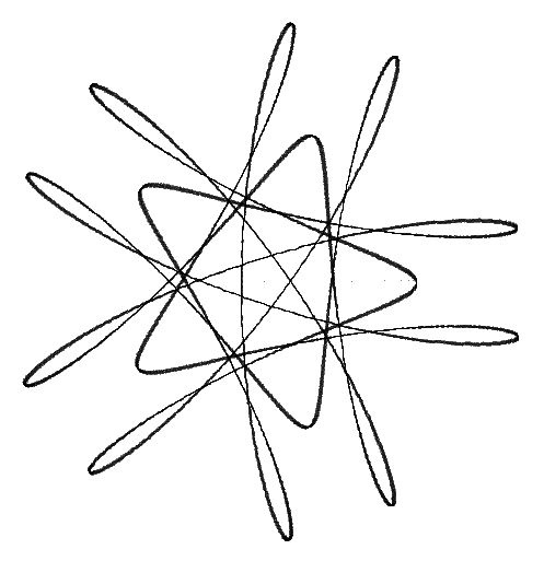
Table: Case 3-1.1 Parameters Assigned (Figure 3-1.1)
Point
P1
P2
P3
Coordinate System
P4
P5
P0
Initial Angle
180
0
0
Angular Increment
0.1300
-0.3900
0.1203
Radius(pixel)
150
110
80
Radius Increment
None
None
None
* Positive angle means clockwise rotation, negative counterclockwise.
[Enlarge the image]

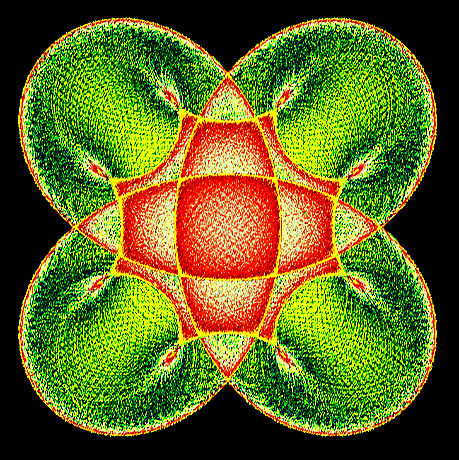
Figure 3-1.1 (12,000,000 iterations)

Table: Case 3-1.2 Parameters Assigned (Figure 3-1.2)
Point
P1
P2
P3
Coordinate System
P4
P5
P0
Initial Angle
0
0
0
Angular Increment
0.1300
-0.3900
0.1203
Radius(pixel)
150
150
80
Radius Increment
None
None
None
* Positive angle means clockwise rotation, negative counterclockwise.
[Enlarge the image]

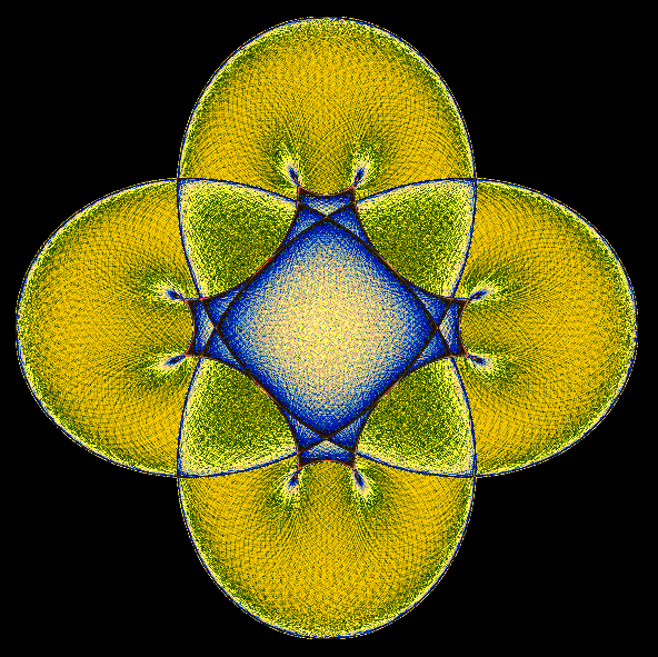
Figure 3-1.2 (12,000,000 iterations)

Table: Case 3-1.3 Parameters Assigned (Figure 3-1.3)
Point
P1
P2
P3
Coordinate System
P4
P5
P0
Initial Angle
0
0
0
Angular Increment
-0.16003
0.48141
-0.04009
Radius(pixel)
150
150
60
Radius Increment
None
None
None
* Positive angle means clockwise rotation, negative counterclockwise.
[Enlarge the image]

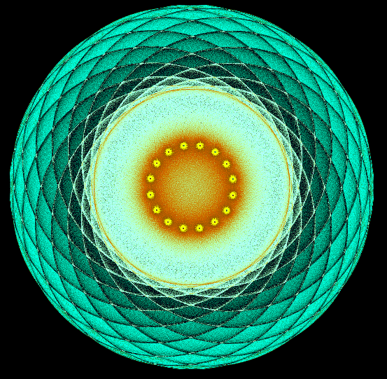
Figure 3-1.3 (12,000,000 iterations)

Table: Case 3-1.4 Parameters Assigned (Figure 3-1.4)
Point
P1
P2
P3
Coordinate System
P4
P5
P0
Initial Angle
0
0
0
Angular Increment
-0.16003
0.48141
-0.00100
Radius(pixel)
150
150
60
Radius Increment
None
None
None
* Positive angle means clockwise rotation, negative counterclockwise.
[Enlarge the image]

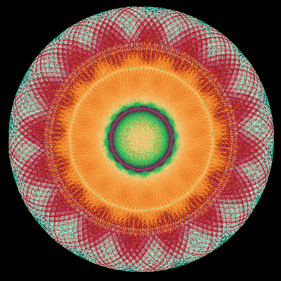
Figure 3-1.4 (12,000,000 iterations)

Table: Case 3-1.5 Parameters Assigned (Figure 3-1.5)
Point
P1
P2
P3
Coordinate System
P4
P5
P0
Initial Angle
0
0
180
Angular Increment
0.36003
-0.24000
0.16
Radius(pixel)
120
180
60
Radius Increment
None
None
None
* Positive angle means clockwise rotation, negative counterclockwise.
[Enlarge the image]

Figure 3-1.5 (85,200 iterations)

Table: Case 3-1.6 Parameters Assigned (Figure 3-1.6)
Point
P1
P2
P3
Coordinate System
P4
P5
P0
Initial Angle
0
0
180
Angular Increment
-1.2003
0.51
0.15
Radius(pixel)
120
180
60
Radius Increment
None
None
None
* Positive angle means clockwise rotation, negative counterclockwise.
[Enlarge the image]

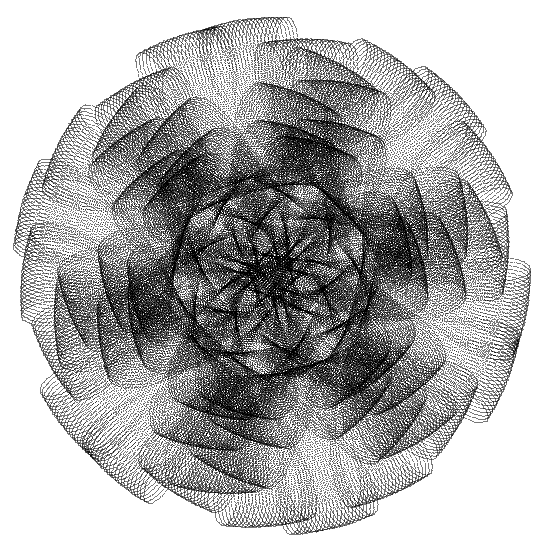
Figure 3-1.6 (270,000 iterations)

Table: Case 3-1.7 Parameters Assigned (Figure 3-1.7)
Point
P1
P2
P3
Coordinate System
P4
P5
P0
Initial Angle
0
90
0
Angular Increment
0.18
-0.24
-0.4207
Radius(pixel)
160
120
80
Radius Increment
None
None
None
* Positive angle means clockwise rotation, negative counterclockwise.
[Enlarge the image]

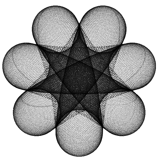
Figure 3-1.7 (521,700 iterations)

Table: Case 3-1.8 Parameters Assigned (Figure 3-1.8)
Point
P1
P2
P3
Coordinate System
P4
P5
P0
Initial Angle
0
90
0
Angular Increment
0.21
0.3509
-0.49
Radius(pixel)
200
40
90
Radius Increment
None
None
None
* Positive angle means clockwise rotation, negative counterclockwise.
[Enlarge the image]

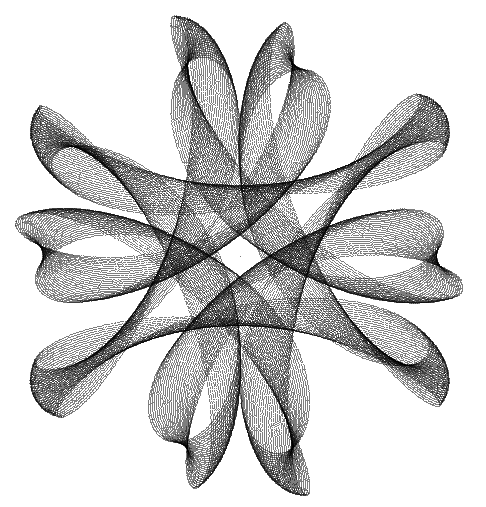
Figure 3-1.8 (148,200 iterations)


CONTENTS:

Index
Introduction
Methodology
Case Study of Aesthetic Forms
Conclusions